
Most enthusiasts familiar with shortwave should have used or heard about BALUN (Balanced to Unbalanced) at some point. A typical application scenario is connecting a BALUN between a balanced antenna and coaxial cable. What is its purpose?
BALUNs serve various functions, such as balancing to unbalance conversion, suppressing common mode current (CMC), impedance transformation, and more. There are different types of BALUNs with distinct purposes. Let’s begin by discussing common mode current.
A BALUN designed to suppress common mode current is also known as a CHOKE (the corresponding term in Chinese is unknown) or current BALUN. Why do we need to suppress common mode current?
Impacts of Common Mode Current
We are aware that Radio Frequency Interference (RFI) needs to be avoided as much as possible. Common mode current, being a form of RFI, can:
- Generate RFI, increasing noise and raising baseline noise
- Affect standing waves
- Weaken reception and transmission signals
- Consume unnecessary power
- Damage equipment
- Potentially cause RF burns at the equipment end
In many cases, poor communication performance may not solely be due to unfavorable environmental factors; common mode current might be the main culprit. How is common mode current generated?
How Common Mode Current is Generated
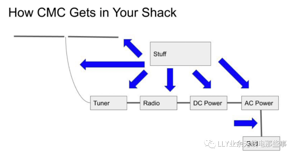
Common mode current can originate from various sources such as power lines, outlets, TVs, electronic devices, etc. Changing currents produce magnetic fields, and changing magnetic fields generate currents. When these sources of changing electromagnetic fields encounter a coaxial cable, the outer shielding of the coaxial cable may conduct current (common mode current).
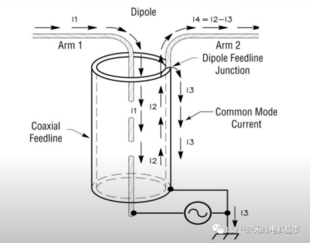
Another scenario, as mentioned at the beginning of the article, occurs when using a balanced antenna (such as a dipole antenna) with an unbalanced cable (such as coaxial cable). One antenna arm (Arm 1) connects to the center conductor of the coaxial cable, while the other arm (Arm 2) connects to the shielding layer, as shown in the diagram. Besides the normal currents I1 and I2 in arms 1 and 2, an additional current I3 is induced in the outer layer of the shielding, known as common mode current. While I1 and I2, being of equal magnitude and opposite direction, do not generate RFI, I3, the common mode current, introduces additional RFI.
Other instances include:
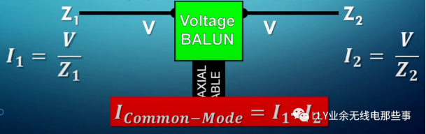
- When the impedance of antenna arms is mismatched, common mode current is generated. In the diagram below, with the same supply voltage, the mismatch in impedance results in different magnitudes for I1 and I2, creating common mode current.
- If there are other RF antennas transmitting around your setup or if your antenna is close to devices, inductive common mode current may be induced in the coaxial cable.
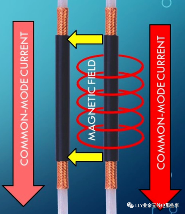
- If there are other cables nearby already carrying common mode current, as shown in the diagram.
How to Suppress Common Mode Current
So, how can we effectively suppress common mode current? In DC circuits, we can use larger resistors, and in AC circuits, we can introduce inductance. Similarly, in terms of suppressing current, we can find ways to change the impedance of the outer shielding of the coaxial cable.
Certainly, we cannot directly add capacitors or inductors to the outer shielding, but there are several alternative methods:
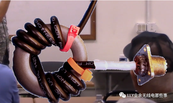
1. Shape the coaxial cable into a capacitor. While this method seems straightforward, its effectiveness depends on the number of turns and corresponding frequencies, making it less convenient. Moreover, it is easily influenced by nearby objects (such as placing your hand close), affecting its practical effectiveness.
2. Introduce a current BALUN.
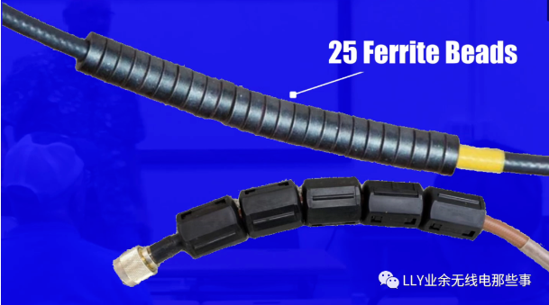
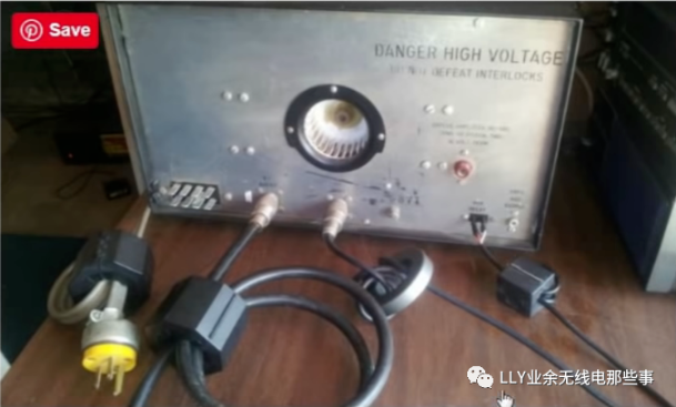
3. Another method involves installing multiple beads on the feed line. The principles behind these methods are the same: altering the impedance of the outer shielding to suppress common mode current.
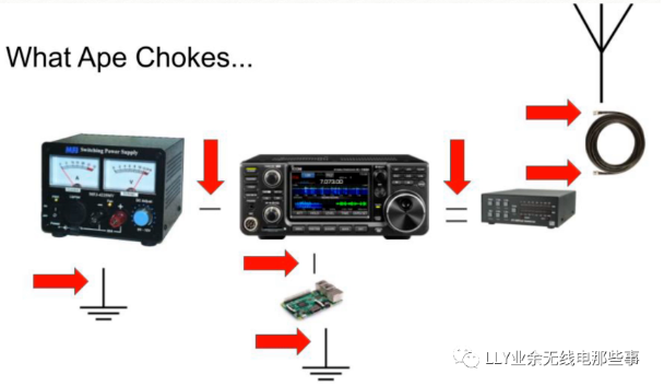
Where to Suppress Common Mode Current?
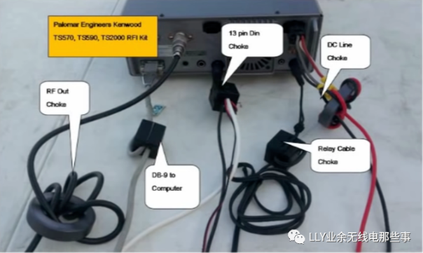
The most common scenario is between the antenna and the feed line. Apart from this, theoretically, installing suppression wherever common mode current is generated is ideal. Let’s take a look at practices from foreign enthusiasts – at the grounding point, between the grounding point and the radio, etc.
Reference Links
- https://www.dxengineering.com/techarticles/balunsandfeedlinechokes/balun-basics-common-mode-vs-differential-mode
- https://youtu.be/W1HFEaWFAOs
- https://youtu.be/s_JHPDA7k5Y
- https://youtu.be/uDu8R-DoOYQ
- https://youtu.be/7GcXca78Etg