
Most of the shortwave radios we we use internally employ the superheterodyne structure for signal up/down conversion in both reception and transmission. Today we are going to talk about the superheterodyne, focusing on analog signal superheterodyne receivers. The SDR architecture of the models, spectrum analyzers, many also use the superheterodyne structure to receive and transmit, we will leave those for later to talk about.
Let’s start with an analogy. The signal we need to transmit (e.g., when we press the PTT button and speak) can be likened to a cake. We need to send this cake, which represents wireless radio waves, to our distant friend, but we can’t send it directly. We need to put it in a cardboard box, and this box is called the carrier wave.
When we talk about commonly used frequencies like 14.270 MHz or 7.050 MHz, these are the frequencies of the carrier waves (the cardboard boxes). The cake we create when we press the PTT button has a frequency of just a few tens of Hz, which doesn’t travel far in the air. So, we take a cardboard box with a frequency of 14.270 MHz and put the cake inside. Through the antenna to send the cake out into the air.
This is the process of transmitting. So, what does this have to do with the superheterodyne structure? Don’t worry, we’ll get to that. In fact, he process of putting the cake into the cardboard box is analogous to how the superheterodyne receiver works. However, when we talk about superheterodyne, we’re usually referring to the receiver. Now, let’s delve into the receiving process.
Our antenna receives a 14.270 MHz courier, which we refer to as the modulated signal. We’ll leave the discussion of signal modulation and demodulation for when we talk about SDR. Can we eat the cardboard box directly? No, we need to remove the cardboard box and eat the cake inside, right? Let’s break down this process.
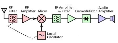
After the signal is received by the antenna, we first pass it through a filter to remove some noise. Because the signal weakens over the transmission distance, we amplify its signal strength by passing it through an amplifier.
Next, we feed the amplified signal into a mixer. Here’s where it’s important: what does a mixer do? As the name suggests, a mixer is a device that combines different signals. The signal we’re receiving has a frequency of Fc, and in the mixer, it mixes with another signal, called the local oscillator (Flo), which is a signal generated internally by the device. The result of mixing is two products: Fc + Flo and Flo – Fc. The frequency difference between the two signals is called the intermediate frequency (IF).
After the mixer outputs both the sum and difference of the two signals, we only need the difference (IF). We send both signals into an IF filter to remove the sum signal. Now we have an intermediate frequency signal. We pass it through another amplifier to further boost its strength.
Finally, we demodulate the intermediate frequency signal, extract the cake, feed it to the speaker, and we can hear the signal. The diagram below shows the process we’re talking about.
What we described, where an incoming signal is mixed with a locally generated oscillating wave to convert the signal’s frequency to an intermediate frequency, is called superheterodyne. Typically, the intermediate frequency is a fixed value, and the local oscillator frequency automatically changes to maintain a constant intermediate frequency, regardless of the received signal’s frequency.
Advantages of the superheterodyne structure:
- High-frequency (signal) to low-frequency (IF) conversion reduces the hardware costs for signal processing.
- The fixed intermediate frequency allows for easy filtering of intermediate frequency signals.
A drawback of the superheterodyne structure is its susceptibility to image frequency interference, This will be discussed later.